Introduction
Texas Instruments have a large range of JTAG-enabled devices. To use some of these devices, a few special considerations are required.
JTAG Connector
TI have a standard 14-way JTAG connector. The best way to connect the XJLink to this connector is to use a 14-way piece of ribbon cable, connecting pins 7-17 of the XJLink to pins 1-11 of the TI connector. Pins 18-20 of the XJLink should be connected to 12-14 of the TI connector, but with a twist such that XJLink Pin 18 goes to TI connector Pin 14:
| XJLink | TI 14-way connector | Function |
|---|---|---|
| 1 2 3 4 5 6 7 8 9 10 11 12 13 14 15 16 17 18 19 20 |
not used not used not used not used not used not used 1 2 3 4 5 6 7 8 9 10 11 14 13 12 |
– – – – – – TMS nTRST TDI GND PD key pin (GND) TDO GND TCK_RET (not used) GND TCK EMU1 EMU0 GND |
Selecting JTAG Mode
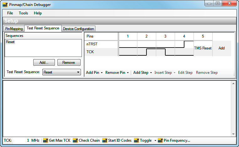
Many TI devices have EMU signals, which are used to select whether the TAP signals are used for JTAG boundary scan testing or processor debug/emulation. To ensure the device can be used for boundary scan testing EMU0 and EMU1 must be latched low while nTRST is low – these signals are latched on the rising edge of TCK. XJTAG is able to support this requirement by defining a Test Reset Sequence as shown below:


