ICT Relay Board
The ICT Relay Board is XJTAG’s recommended solution when there is a requirement to allow multiple instruments to be connected to the TAP control signals on a Unit Under Test (UUT). It allows both an XJTAG XJLink2 JTAG controller and another piece of test/programming equipment access to the TAP control signals, while ensuring the UUT is fully isolated from the disconnected instrument.
Key benefits
Switches connections to allow instruments to share JTAG TAPs
Provides full isolation (signals and ground)
Configurable control pin to switch between instruments
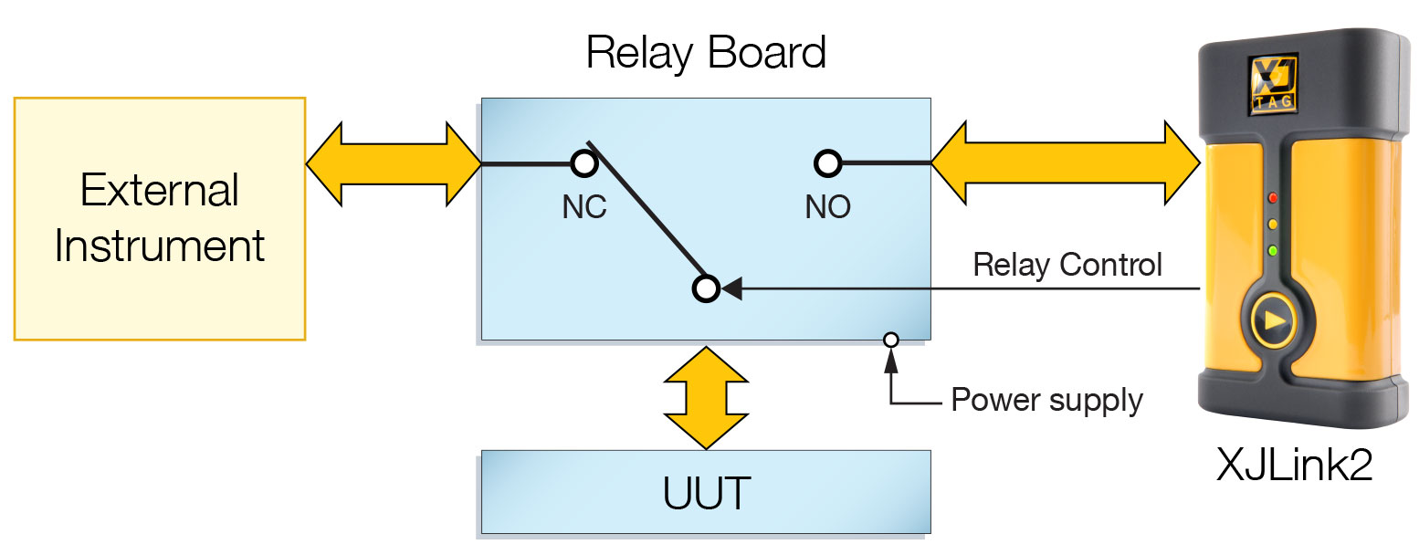
System Overview
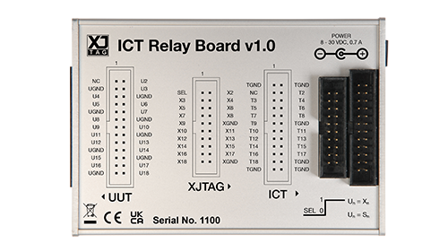
The adjacent figure shows a block diagram of the Relay Board, highlighting the following marked connectors:
- UUT – 26 way connector with 17 active signals and 8 ground pins.
- Instrument connector 1 – 24 way connector with 17 active signals and 6 ground pins.
- Instrument connector 2 – 20 way (XJTAG) connector with 17 active signals, 2 ground pins and the relay control signal.
- Power – DC power connector (centre positive) 8 V to 30 V.
Operation Summary
In its default state (either unpowered or powered but not being actively controlled) the Relay Board connects Instrument 1 to the UUT. The connection is switched using a setting in the XJTAG project, disconnecting Instrument 1 and connecting Instrument 2 (the XJLink2) to the UUT.
At the end of XJTAG testing the relays revert to their default state, connecting Instrument 1 to the UUT. This ensures the UUT is isolated from the XJTAG system during bed-of-nails testing or other operation.
The Relay Board provides full isolation. As well as isolating the active signals used for the TAP control signals, it also switches the UUT ground between the connected instruments.
Relay Control
The relay connection is, by default, controlled using pin 1 on the connector for Instrument 2, the XJLink2 connector. The Relay Board switches from connecting Instrument 1 to the UUT to connecting Instrument 2 to the UUT when pin 1 on the Instrument 2 connector is driven high. The XJLink2 is completely isolated from the UUT until triggered, and is always completely isolated from Instrument 1.
Within an XJDeveloper project this can be achieved in one of three ways:
- Set the function of pin 1 to be Power On
- Set the function of pin 1 to High
- Set the function of pin 1 to be PIO and then control the pin at the start of the Test Reset Sequence to be high.
The function of pin 1 is configured on the Pin Mapping screen in XJDeveloper.
UUT Connection
When fabricating the connections from the UUT to the Relay Board it is strongly recommended to use twisted pair cables. Each active UUT signal is located near to a ground signal on the connector to make this easy to implement. To ensure optimum signal integrity, all of the ground wires from the twisted pairs should be connected to ground pins or test points as close to the active signals as possible on the UUT.
If this is not done, signal integrity issues caused by large loop areas can occur – see Signal Integrity article for more details.
Product code:
ICT-0010. Please contact your local distributor for a quote.
Compatible with:
| XJLink-PF40 | XJLink2 | PXI-XJLink2 | XJQuad |
| Yes (via XJA-0030/1) | Yes | Yes (via XJA-0032) | Yes |