Some JTAG devices require a specific sequence of states to be applied to their TAP signals to put them into JTAG-compliant mode. This application note describes how this can be performed using a Test Reset sequence.
Creating Test Reset Sequences
Test Reset sequences can be defined using the JTAG Chain Debugger. They are stored as part of the pin mapping file (*.xjpm) and can be used by the other XJTAG applications. They can also be created in XJDeveloper’s pin mapping screen or XJAnalyser’s Project Setup Wizard.
This application note will use the example of the Texas Instruments TMS320 range of DSPs. To ensure the DSP detects a rising edge on nTRST, some devices need the nTRST TAP signal to be held low for a few TCK cycles before it is set high.
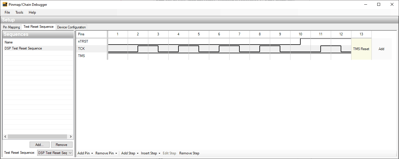
Figure 1 – Creating a Test Reset Sequence Using JTAG Chain Debugger
After the TAP signals have been mapped to the JTAG controller’s pins (using the Pin Mapping tab), the sequence is created in the Test Reset Sequence tab as a series of steps, each one allowing one of the TAP signals to change state:
- Create a new sequence using the Add… button and provide a name.
- Add the relevant TAP signals from the Add Pin menu at the bottom of the pane. In this example, TCK and nTRST are needed. However, it is good practice to also include TMS to ensure it is kept high during the sequence.
- Add a number of steps to the sequence and create the signal transitions by double-clicking in the cells (or using the space bar), which toggles the signal’s state between high, low, and high impedance. In this example, four TCK rising edges have been provided before nTRST is taken high so that the requirements of the particular device are met.
- A TMS reset should be added at the end of the sequence using the Add Step menu at the bottom of the pane.


